ZnO Piezoelectric Pressure Sensor
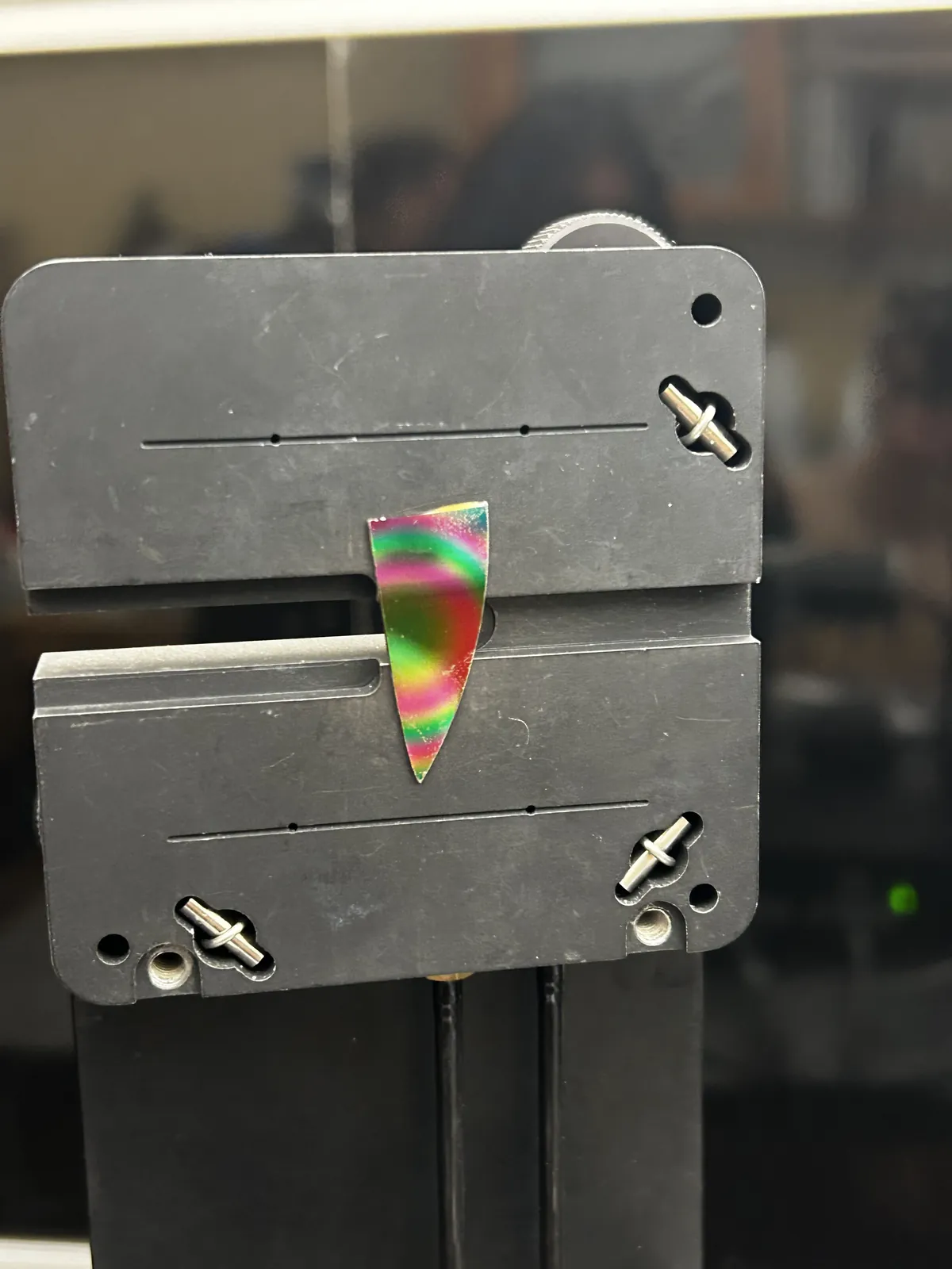
Our group fabricated a thin-film FTO/ZnO/Ag piezoelectric pressure sensor. I built the amplifier that could hear it, wrote the firmware that could catch it, and then proved against three separate controls that the signal was real.
Fabrication
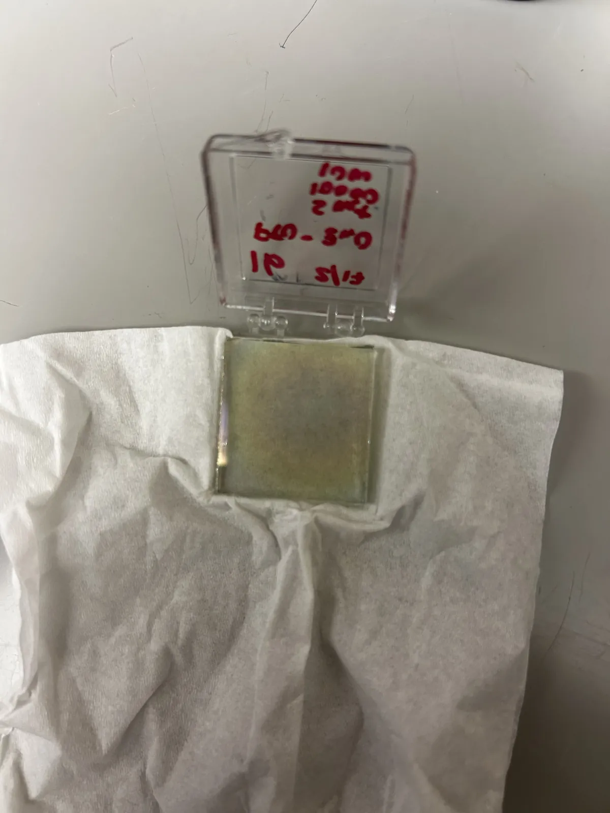
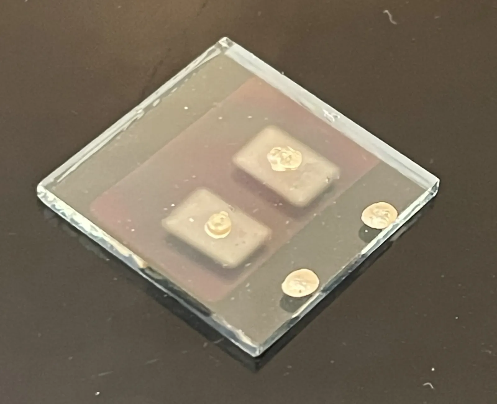
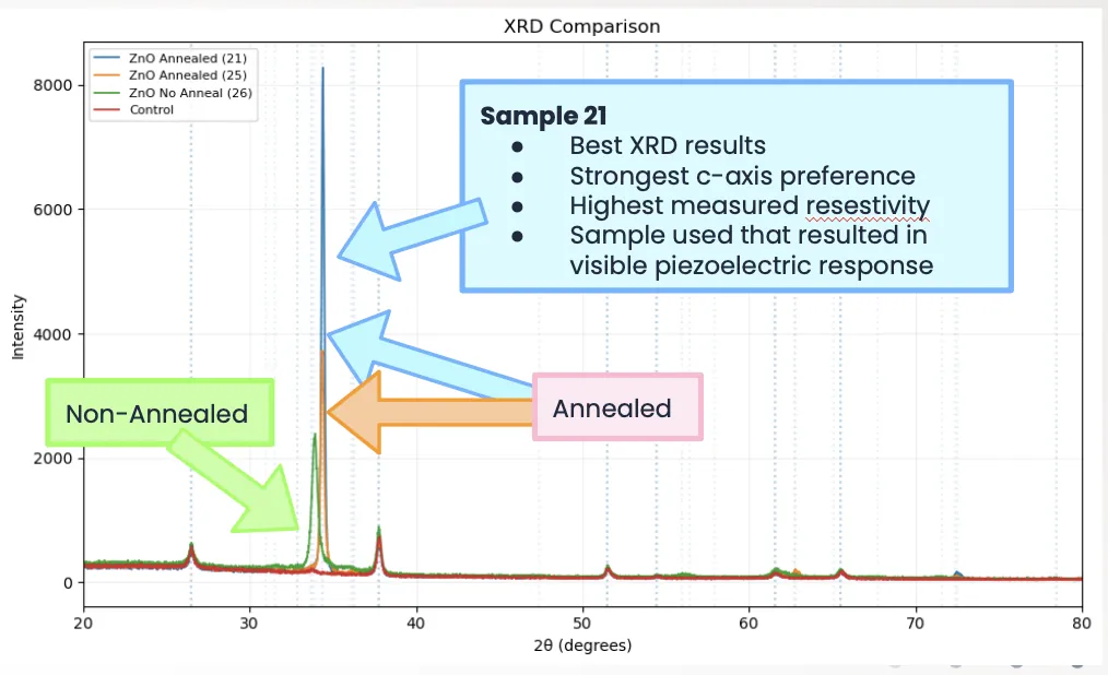
The sensor is a thin-film stack: a fluorine-doped tin oxide bottom electrode on glass, a ZnO piezoelectric layer grown by pulsed laser deposition, and a silver top electrode. Annealing at 500 C aligned the crystal along its c-axis, the direction that generates the most charge, and X-ray diffraction confirmed it. Squeeze the ZnO and it generates charge; the electrodes collect it. The project was joint work with Carter Chapman, Saki Male, and Ingrid Russell.

Electronics and firmware
Depositing and fabricating the film was a group effort. The electrical characterization was mine. Piezo transients from a film this thin are fast and only tens of microvolts at the source, at or below the noise floor of the lab, and the oscilloscope and the other standard lab tools could not resolve them. So I designed and built the voltage measurement method myself: a custom AD620 instrumentation amplifier circuit with a calibrated gain of 62.5 and the signal conditioning around it, feeding Arduino firmware I wrote that reconfigures the onboard ADC for 2 kHz sampling, tracks the drifting baseline, and logs the millisecond transients that a multimeter could never catch. The hardware side of this project was my side.
Proving it was real
No single tap stood out above the noise, but rhythmic tapping at 2 Hz produced a voltage pattern locked to my hand: change the tempo and the period changed, stop and it vanished. I then validated it against three independent controls: an insulating tape layer, an electrode polarity reversal, and taps on the bare glass away from the device. A real piezo signal must flip cleanly when the leads flip, and mine did. All three controls behaved exactly as a genuine piezoelectric response demands.
The debugging story
The response was real but far smaller than theory predicts. My DC measurements across the sample set traced the attenuation to parasitic conduction through the film: even the best device measured about 107 kilohms where an ideal piezoelectric capacitor would read megohms, so most of the generated charge drains away before it can build a voltage. Annealing raised both the crystal quality and the resistance, which is why only the best annealed sample gave a detectable signal. That is the kind of fault you only find by refusing to accept that something mostly works.